All CC wells will be advanced an additional 20 feet into the Hammett Shale (HS) for geophysical logging. The HS portion will be plugged with bentonite prior to well installation.
During the well installation process, selected coreholes/boreholes will be drilled in a manner so the subsurface core will be retrieved and lithologically described. As needed, protective surface casing will be utilized to keep the lithologic formations hydraulically isolated, and to minimize the potential downward migration of contaminants due to drilling technique and well construction.
Other actions performed at select locations will include geophysical logging and downhole video camera surveys. In addition, discrete interval groundwater samples will be obtained to evaluate the occurrence and stratification of contaminants within the aquifer. Table 1 lists the estimated drilling depths and requirements for each well. These values are not absolute, and are estimated for costing purposes.
2.1 - Overview of Well Installations
Each cluster may not be drilled in its entirety before proceeding to the next cluster. The order of drilling will depend on equipment availability and drill site logistics. At any given time, multiple rigs may be performing coring and well installations at cluster locations. The identified procedure for installing each well cluster will follow a phased approach. When deemed necessary, protective surface casing will be installed in each borehole prior to proceeding to the next hydrologic unit, with a potential exception of the Bexar Shale formation when drilling to the Cow Creek formation.
Ideally where rock coring, geophysical logging, and video surveying occur, all downhole geologic information will originate from a single corehole that ultimately becomes the deepest well at that cluster location. However, extenuating circumstances may warrant coring to occur over multiple well positions at a single cluster location. Past circumstances justifying changes in procedure include rig access issues, areas of known faulting that may affect the lithologic contact depths between wells within a cluster, and significant changes in land surface elevation between wells within a cluster.
Any surface casing utilized will be composed of welded low-carbon steel pipe. Final diameter well casings will be composed of nominal 4-inch Schedule 80 PVC. The screen material will be wire-wrapped stainless steel within an appropriately sized filter pack. All annular grout seal will be emplaced via tremie pipe. Wells will be completed with 4-foot square concrete pads with locking well protectors and protector posts in accordance with state regulations. A rounded brass monument will be placed in each monitoring well concrete pad to serve as a permanent benchmark. All wells will be secured as soon as possible after drilling with corrosion-resistant locks. The locks will all be keyed the same. CSSA will provide locks and keys following completion of each well.
A full decontamination of equipment will take place before proceeding to the next hydrologic unit. A minimum of 24 hours will pass after the emplacement of casing grout before proceeding to the next hydrologic unit. Decontamination will take place between drilling of hydrologic zones or relocating to different well clusters.
Table 1 - Estimated Quantities of Drilling Requirements
| Monitoring Well | Screened Interval | Core (Qty) | 4� Casing with 25� Screen (feet) | 8� Carbon Steel Casing | Discrete Sample � (Qty) | Geophysical Log | Camera Survey | Install Pump | Install Transducer |
| CS-MW-1-BS | Bexar Shale | � LGR, BS (383) | 373 | 320 | | � (1) | | Yes | No |
| CS-MW-1-CC | Cow Creek | � CC (80) | 445 | 320 | � (4) | � (1) | | Yes | No |
| CS-MW-2-CC | Cow Creek | � CC (80) | 474 | 340 | � (4) | � (1) | | Yes | Yes |
| CS-MW-11-LGR | L. Glen Rose | � LGR (370) | 360 | | � (3) | � (1) | � (1) | Yes | Yes |
| CS-MW-12-LGR | L. Glen Rose | � LGR (370) | 360 | | � (4) | � (1) | | Yes | Yes |
| CS-MW-12-BS | Bexar Shale | � BS (80) | 430 | | | � (1) | | Yes | No |
| CS-MW-12-CC | Cow Creek | � CC (80) | 500 | | � (4) | � (1) | | Yes | Yes |
| CS-MW-13-LGR | U/L. Glen Rose | � LGR (300) | 300 | | � (5) | � (1) | � (1) | No | No |
| CS-MW-14-LGR | U/L. Glen Rose | � LGR (300) | 300 | | � (5) | � (1) | � (1) | No | No |
| CS-MW-15-LGR | L. Glen Rose | � LGR (395) | 385 | | � (3) | � (1) | � (1) | Yes | Yes |
| CS-MW-15-CC | Cow Creek | � BS/CC (150) | 525 | | � (3) | � (1) | � (1) | Yes | Yes |
| CS-MW-16-CC | Cow Creek | � BS/CC (150) | 450 | 320 | | � (1) | | Yes | No |
| CS-MW-17-LGR | L. Glen Rose | � LGR (380) | 370 | | | � (1) | | Yes | Yes |
| CS-MW-18-LGR | L. Glen Rose | � LGR (380) | 370 | | � (3) | � (1) | � (1) | Yes | Yes |
| CS-MW-19-LGR | L. Glen Rose | � LGR (390) | 380 | | � (3) | � (1) | | Yes | Yes |
| CS-MW-20-LGR | U/L. Glen Rose | � LGR (300) | 300 | | � (5) | � (1) | � (1) | No | No |
| CS-MW-21-LGR | U/L. Glen Rose | � LGR (300) | 300 | | � (5) | � (1) | � (1) | No | No |
| CS-MW-1-LGR | L. Glen Rose | Well Upgrade | 313 | | | | | Existing | Yes |
| CS-MW-2-LGR | L. Glen Rose | Well Upgrade | 343 | | | | | Existing | Yes |
| CS-MW-16-LGR | L. Glen Rose | Well Upgrade | 310 | | | | | Existing | Existing |
| CS-9 | LGR/BS/CC | Well Upgrade | | | | | | | Yes |
| CS-10 | LGR/BS/CC | Well Upgrade | | | | | | | Yes |
| CS-11 | LGR/BS/CC | Well Upgrade | | | | | | | Yes |
| CS-G | L. Glen Rose | Well Upgrade | | | | | | Yes | |
| CS-H | L. Glen Rose | Well Upgrade | | | | | | Yes | |
| Totals: | 4,488 | 7,598 | | 51 | 17 | 8 | 15 | 14 |
| Casing Requirements All wells will be completed with 4-inch Schedule 80 PVC and 25 feet of 0.050� wire-wrapped stainless steel screen. Primary and secondary casing will be low-carbon steel with welded joints. Cow Creek wells will be triple-cased, and Bexar Shale wells and CS-MW-11-LGR will be double-cased. The remaining Lower Glen Rose wells will be single-cased. Assumptions Coring, geophysical logs, and video surveys may be composited within a cluster (*) denotes locations were coring will resume at a depth comparable where prior drilling ceased. Geophysical and video surveys will require multiple mobilizations per cluster to log the entire stratigraphic sequence penetrated. |
At this time, it is anticipated that the drilling effort will result in 13 single-cased wells and four double-cased wells (CS-MW1-BS, CS-MW1-CC, CS-MW2-CC, and CS-MW16-CC). Figure 2 illustrates three potential well completion types. Welded low-carbon steel protective casing will be installed no more then 10 feet into the underlying formational member. The actual casing depth will be dependent on the nature of the geologic contact. Geophysical data will be the key information in identifying the optimum depth to install the casing.
2.2 - Monitoring Well Specifications
2.2.1 Single-Cased Wells
Single-cased wells will be drilled using air rotary methods until the hole has advanced an estimated 120 feet to 525 feet into the LGR, BS, or CC formation. The actual installation depth will be pre-determined by the on-site geologist based on results of the corehole lithology and/or geophysical logging as indicated on Table 1.
In general, a single-cased monitoring well will be constructed with a nominal diameter of 4 inches, consisting of a Schedule 80 PVC riser coupled with 25 feet of stainless steel screen. However, when necessary because of the potential threat of downward contaminant migration, an LGR, BS, or CC well may be completed as a double-cased well (see next section). The well will be completed within an open borehole no less than 7-7/8 inches in diameter. Casing and screen will be centered within the borehole using stainless steel centralizers at 50-foot intervals. The diameter of the wells will allow for installation of a standard 3-inch groundwater pump sufficiently sized to pump groundwater at that depth. A construction schematic for the single-cased LGR wells is included in Figure 2. Specifications for installation of the well casing and screen follow in the �Well Construction Requirements� section of this document.
2.2.2 Double-Cased Wells
Where necessary, double-cased wells will be drilled using air rotary methods until the hole has advanced into the either the LGR or BS formations as dictated by the drilling location. The actual installation depth will be predetermined by the on-site geologist based on results of the corehole lithology and/or the geophysical logging. At this time, it is anticipated that CS-MW1-BS, CS-MW1-CC, CS-MW2-CC, and CS-MW16-CC will require double-cased completions to isolate the LGR from the target depth.
The drilling subcontractor will drill the boreholes using air rotary methods until the hole has advanced 5 to 10 feet below the predetermined depth of the LGR / BS contact, or other depth specified by the on-site geologist. The borehole will be reamed to a 12-1/4 inch diameter and an 8-inch casing installed from ground surface to 5 to 10 feet below the LGR/BS contact, to ensure a complete seal. The primary protective casing in the well will be no larger than 8-inch inside diameter (ID) (8-5/8 inch outside diameter (OD)) low carbon steel casing completed within a borehole with a nominal diameter of 12-1/4 inches. This casing completion will result in an annular space of 1-13/16 inches. The casing will be centered within the borehole using steel centralizers at 50-foot intervals. The casing will be grouted, then left to cure at least 24 hours before advancing the boring.
Following curing, the drilling subcontractor will drill the borehole until it has advanced to the predetermined depth using a 7-7/8-inch drill bit. Actual installation depth will be determined by the on-site geologist based on results of the corehole lithology and/or the geophysical logging. The actual monitoring well will be constructed with a nominal diameter of 4 inches, consisting of a Schedule 80 PVC riser coupled with 25 feet of stainless steel screen. The well will be completed within an open borehole no less than 7-7/8 inches diameter. The casing and screen will be centered within the borehole using stainless steel centralizers at 50-foot intervals. The diameter of the wells will allow for installation of a standard 3-inch groundwater pump, which will be sufficiently sized to pump groundwater at that depth. A construction schematic for the double-cased wells is included in Figure 2. Specifications for installation of the well casing and screen follow in the �Well Construction Requirements� section of this document.
2.2.3 Triple-Cased Wells
Although triple-cased wells are not anticipated, the drilling subcontractor will drill and continuously sample the borehole using air rotary methodology until the hole has advanced 10 feet into the BS. Following coring, the borehole will be logged with the geophysical tool and downhole video equipment at locations specified in Table 1.
The drilling subcontractor will ream the borehole to a 16-3/8 inch diameter and install 12-inch ID casing from 5 to 10 feet below the LGR / BS contact to the surface. The casing will be no larger than 12-inch ID (12-3/4 inch OD) steel casing completed within a borehole with a nominal diameter of 16-3/8 inches. This casing completion will result in an annular space of 1-13/16 inches. The casing will be centered within the borehole using centralizers at 50-foot intervals. The casing will be grouted, then left to cure at least 24 hours before advancing the boring.
As a last resort, an environmentally safe foaming agent may be utilized to facilitate removal of cuttings from larger-diameter boreholes. Prior to use of the foaming agent, approval from CSSA and AFCEE will be required. The drilling subcontractor will make adequate provisions for the containment, control, and de-foaming of any foam exiting a wellhead.
Following grout curing, the coring will resume until it has advanced a maximum of 10 feet into the CC limestone. The geophysical subcontractor will then log the hole with the geophysical tool and downhole video equipment as specified in Table 1.
The drilling subcontractor will ream the bore hole to 12-1/4 inch diameter and install 8-5/8 inch ID casing from 5 to 10 feet below the BS / CC limestone contact to the surface. The second string of casing will be no larger than 8-inch ID (8-5/8 inch OD) low carbon steel casing completed within a borehole with a nominal diameter of 12-1/4 inches. This casing completion will result in an annular space of 1-13/16 inches. The casing will be centered within the borehole using steel centralizers at 50-foot intervals. The casing will be grouted, then left to cure at least 24 hours before advancing the boring.
Following grout curing, the coring will resume until it has advanced 20 feet into the HS. The geophysical subcontractor will then log the hole with the geophysical tool and downhole video equipment as specified in Table 1.
The HS portion of the borehole will be plugged back with bentonite pellets. The borehole will then be reamed using a 7-7/8-inch bit until the hole has advanced to the predetermined depth of the CC / HS contact. The actual installation depth will be pre-determined by the on-site geologist based on results of the corehole lithology and/or geophysical logging. The monitoring well will be constructed with a nominal diameter of 4 inches, consisting of a Schedule 80 PVC riser coupled with 25 feet of stainless steel screen. The well will be completed within an open borehole no less than 7-7/8 inches diameter. The casing and screen will be centered within the borehole using stainless-steel centralizers at 50-foot intervals. The diameter of the wells will allow for installation of a standard 3-inch groundwater pump, which will be sufficiently sized to pump groundwater at that depth. A construction schematic for the triple-cased CC wells is included in Figure 2. Specifications for installation of the well casing and screen follow in the �Well Construction Requirements� section of this document.
2.2.4 Well Construction Requirements
The interior 4-inch ID PVC casing and 304 stainless steel screen will be installed in each well (17 wells total) to limit the amount of open borehole to less than 27 feet. The casing and screen will be centered within the borehole using stainless steel centralizers at 50-foot intervals. All well casings, screens, and end caps will be flush-threaded, and will not require the use of any glues or solvents. All well material will be certified �clean� by the manufacturer, and will remain within its original packaging until the time of downhole installation.
The well riser will consist of nominal 4-inch Schedule 80 PVC (3.83-inch ID) with flush-threaded joints. The well screen will be constructed of 4-inch ID 304 stainless steel wire-wrapped screen with a slot size of 0.050-inches (50-slot), with no more than a 25-foot intake. While the use of Schedule 80 PVC provides high strength at lower cost than steel, the slightly smaller ID of the schedule 80 PVC casing will not accommodate a standard well pump typically used in wells with a nominal diameter of 4 inches. A smaller pump that will fit within a 3.75-inch well and sufficiently sized to pump groundwater at that depth will be available for well development.
The annular space will be filled with an 8/16-mesh filter pack from the base of the borehole to a height of 2 feet above the top of the screened interval. According to the manufacturer�s grain-size analyses of its product, less than 4 percent of the 8/16-mesh sand products will pass through a wire-wrapped screen with 0.050-inch slot apertures. The sieve analysis from the product manufacturer is included in Appendix A. According to Groundwater and Wells (Driscoll 1986), at least 90 percent of the filter pack should be retained by the slot openings of the well screen.
The filter pack will be emplaced via tremie pipe from the base of the borehole to the top of the designated screened zone. The height of the filter pack will be monitored continuously during emplacement using a weighted measuring device. The amount of required filter material will be calculated prior to emplacement of the filter pack. Given the well construction parameters (7-7/8 inch borehole and 4-1/2 inch OD screen), approximately 24.5 pounds of sand will be required for each foot of the filter pack height. As an example, a filter pack height of 27 feet will require approximately 660 pounds of 8/16-mesh silica sand.
A 100 percent sodium bentonite seal with a maximum thickness of 5 feet will be emplaced within the borehole above the filter pack. The bentonite will be dropped into the borehole from the surface at a rate sufficient to avoid clumping and bridging, and will settle through the water column by gravity. The bentonite seal will be allowed to fully hydrate per the manufacturer�s specifications before grouting activities commence.
Beginning with small lifts (less than 250 gallons), a Portland cement/bentonite grout mixture will be slowly pumped into the annular space using a side-discharge tremie pipe. The grout mixture will be mixed in the following proportions: 94 pounds of neat Type I Portland or American Petroleum Institute (API) Class A cement, not more than 3 to 5 pounds of 100 percent sodium bentonite powder, and not more than 7 gallons of potable water. A properly mixed batch of grout should yield 10.8 gallons per 94-pound sack of Portland at a density of 14.5 pounds per gallon. This proportion of grout yields approximately 1.45 cubic feet per sack of Portland cement. The volume of grout will be calculated prior to emplacement. The slurry will be injected until grout flows freely at the surface. The annular space will be checked periodically for settlement, and will be topped off as needed to no greater than 2 feet bgl. The grout will be allowed to cure for at least 48 hours prior to well development.
2.2.5 Westbay� Multi-Port Well Construction Requirements
To better profile the upper 300 feet of the Glen Rose in the vicinity of AOC 65, a multi-port sampling system will be utilized to obtain discrete pressure and groundwater data from isolated zones. To install a Westbay� Multi-port (MP) System, a nominal 4-inch diameter corehole is drilled to 300 feet below grade using methods described in Section 2.4. Each corehole will be geophysically logged and a video survey completed prior to the installation of an MP well. Careful consideration with respect to faults, fractures, water-bearing zones, and karstic features will be considered when designing the MP construction. All lithologic, geophysical, and video logs will be carefully reviewed before installation. The design will be agreed upon by CSSA, AFCEE, Westbay, and Parsons for each well before commencing installation. The drilling subcontractor will install the MP well under direct supervision of Westbay personnel.
The drilling subcontractor will adequately develop the corehole to remove any sediment or drilling fluids. The MP wells will be constructed by Westbay, and documented and checked by Parsons. Westbay will install the wells, inflate the packers, and demonstrate that the zones are hydraulically separated.
The MP System consists of hydraulic packers and casing components permanently installed in the borehole, portable pressure measurement and sampling probes, and specialized tools. The casing components include casing sections of various lengths, regular couplings with different capabilities, and packers, which seal the annulus between the monitoring zones. The packers are water-filled, and permanently isolate the monitoring point from the remainder of the corehole.
The MP casing is supplied in a number of different lengths to provide flexibility in establishing the position of monitoring zones and associated seals in the borehole. Common nominal casing lengths are 2-foot, 5-foot, and 10-foot sections. The casing ends are machined to mate with MP System couplings. All couplings (regular, valved, and end caps) incorporate O-rings for a positive hydraulic seal. No adhesives are used when joining casings and couplings. Valved couplings include measurement ports and pumping ports. The valved couplings incorporate an internal, helical shoulder for the accurate location of probes and tools in the well.
Measurement port couplings are used where pressure measurements and fluid samples are required. The measurement ports incorporate a valve in the wall of the coupling, a leaf spring that normally holds the valve closed, and a cover plate of screen that holds the spring in place. When the valve is opened, an access port is provided for the groundwater to enter the coupling. Pumping ports are used where the injection or withdrawal of larger volumes of fluid than would be reasonable is needed through the relatively small measurement port valve (such as for purging or hydraulic conductivity testing). Pumping ports incorporate a sleeve valve, sealed by O-rings, which can be moved to expose or cover slots that allow groundwater to pass through the wall of the coupling. A screen is normally fastened around the coupling outside the slots.
Westbay will provide 3-day training to CSSA and Parsons personnel in the correct operation and maintenance of the sampling equipment. The sampling equipment will be leased from Westbay for a term extending between 1 and 3 years.
2.3 - Contingency Planning
Inevitably, unforeseen contingencies will arise which will require deviations or modifications to the SAP. Some events may require immediate action, while others may be less severe and can be handled in a roundtable fashion with CSSA, AFCEE, USEPA, and the TNRCC. While it is not possible to predict all unexpected field conditions, two scenarios are worthy of discussion: the use of drilling additives and encountering contaminated perched groundwater or dense non-aqueous phase liquids (DNAPLs).
2.3.1 Drilling Additives
Drilling equipment that uses compressed air to remove drill cuttings is sometimes unable to properly clean boreholes. This is based on factors such as boring diameter, amount of water the formation is producing, composition of the formation, pressure of compressed air, and volume of compressed air. Products are available to aid the recovery of drill cuttings. One of these products, QuickFoam�, will be available for use if deemed necessary. Isopropanol and ethanol are the primary active ingredients in the foaming agent commonly used in water well drilling. The decision to use QuickFoam will be made only after CSSA, AFCEE, and the USEPA have given approval. At present, the foaming agent will only be used as a last resort to flush out cuttings from large diameter boreholes. A fingerprint chemical analysis is included in Appendix B.
2.3.2 Perched Groundwater
The initial phase of drilling (RL83) demonstrated that perched water may be encountered depending on location and recent climatic conditions. Therefore, an important consideration in drilling boreholes/coreholes is determining whether perched groundwater zones are present and, if so, whether contaminants are harbored within that zone. As necessary, perched groundwater will be kept isolated to prevent cross-connection or cross-contamination between water-bearing units. The following procedure will be used to meet these goals.
From the surface, drilling/coring will proceed as described in the Work Plan. During air rotary drilling, air returns and retrieved core will be inspected for indications of water. This procedure can be difficult since water is continuously being introduced during the �misting� process, which allows the core to get significantly moist. In the vicinity of Building 90, drilling within the vadose zone will be completed without the use of �misting� to aid in the detection of isolated or perched water-bearing zones.
As a daily procedure, the borehole will be monitored for accumulation of groundwater or evidence of contamination before commencing drilling activities. Groundwater accumulation will be measured using either an electric level measuring device, a weighted surveying tape, or a Teflon� bailer. If perched groundwater is encountered or accumulated, an attempt will be made to obtain a representative grab sample of the groundwater. CSSA will be notified when perched water is encountered and a sample obtained.
If perched groundwater in the borehole/corehole is indicated, a sample will be obtained and submitted for VOC analyses using a 24-hour turn around time. When drilling in the Building 90 area (CS-MW13, -14, -15, and -16), drilling will be suspended until the sampling results are provided by the laboratory and reviewed. If the analytical data indicate contamination at that depth, CSSA may opt for installation of a single-cased groundwater well to monitor that zone. Implications of a contaminated perched zone may preclude completion of the well cluster if there are sufficient concerns regarding cross-contamination between hydrostratigraphic units. Those issues will be reviewed and addressed on a case-by-case basis with CSSA, AFCEE, and the USEPA. Further drilling and collection of additional grab water samples using packers to isolate selected water producing zones would be considered at this time.
However, if the initial sampling of perched water does not indicate the presence of contaminants, the borehole/corehole will be continued unless PID, visual, or olfactory evidence indicates an encounter with significant contamination. At that time, coring would be suspended and a single-cased well may be installed to monitor the affected zone. Otherwise, the well cluster will be completed in accordance with the Work Plan.
In addition to the primary surface casing, provisions are provided in the cost estimate for 600 feet of additional temporary casings. During the coring of the pilot holes, temporary casing may be prudent to seal off perched zones since borehole advancement is significantly slower than the remainder of the drilling. Temporary casings could be installed by those methods described in the Work Plan for LGR Monitoring Well Installation (Parsons ES 1996), which utilizes a small diameter surface casing temporarily emplaced with a bentonite seal. Temporary casing would be removed prior to installation of the larger diameter permanent steel casing.
If conditions warrant, additional permanent surface casings may be considered for well completions in contaminated areas. These instances will be reviewed on a case-by-case basis with CSSA, AFCEE, USEPA, and the TNRCC to design a well construction acceptable to all interested parties.
2.4 - Core Sample Collection
 The deepest hole at selected clusters (Table 1) will be drilled first and referred to as the �corehole.� The corehole will be continuously sampled using a nominal 4-inch diameter core barrel with air rotary drilling methods. Upon retrieval, the core will be immediately screened with a PID to identify any potential zones of VOC contamination. Sample intervals will be identified quickly, selected for laboratory analyses, and samples will be obtained as soon as the PID screening is complete.
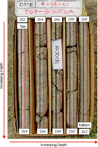
Every reasonable attempt will be made to recover the correct orientation of the core samples. Each core will be measured for recovery, and an attempt to identify any missing sections will be made with the driller. Where the core is broken and fragmented, an attempt to reposition the correct orientation of the segments will be made before marking the core. While still in the core barrel, the core sample will be marked with a pair of differently colored (red and black) ceramic marking pencils in a fashion that results in a continuous parallel line down the length of the core. The red marking will be on the right side of the parallel lines when viewing the core from top to bottom. The coloration scheme will allow any piece of core to be correctly oriented in the vertical plane (red on right side). Marked rock cores will be stored in standard core boxes, and missing sections of the core replaced with spacers. Both the core box base and core top will be appropriately-labeled with the well identification, core depth, date, and geologic formation origin. Additionally, the core box base will be sufficiently labeled so the top and bottom of the core are clearly evident. Depths for each 2-foot broken interval should be written on the core box base in a relative position that corresponds with the dividers. Styrofoam spacers will be labeled with the missing interval or sampling information and appropriately positioned within the retrieved core.
CSSA will supply 10-foot core boxes, and Parsons will label them appropriately with date, time, depth, and drilling information relevant to the retained sample. Each section of core will be marked with a corresponding depth, and electronically recorded using the CSSA digital camera. The top portion of the core interval starts at the upper left hand corner of the core box, with increasing depth progressing downwards and toward the right, until the lower portion of the core interval is at the lower right hand corner of the core box base (as shown above). The retained core will be prepared for storage and archival at the University of Texas-San Antonio core library.
2.5 - Sample Analysis
Based on the revised DQOs, no samples for VOCs and inorganic analyses will be obtained from subsurface soil/rock cores. Past experience has shown contamination to be negligible at depth. However, the on-site geologist is given authority to submit discretionary soil/rock samples suspected to be contaminated or of unique interest. Those sample depths will be based on field measurement of volatiles (using a PID), visible contamination or staining, zones of fracturing, secondary porosity features, or intervals of saturation. All definitive data samples will follow the full QA/QC procedures defined in Sections 2, 3, and 4 of the SAP (Volume 1-4 of the Environmental Encyclopedia). Definitive sample data (Table 3) will be reported by the laboratory within a standard 21-day turn-around-time, and must be marked as such on the chain-of-custody (COC).
A total of 51 groundwater samples collected from the discrete interval groundwater sampling tests, and another 160 IDW samples (estimated at 120 water and 40 solids samples) will be analyzed for VOC contamination. These samples will be considered �screening� samples and not all will require complete verification or validation. All screening samples will be analyzed for the VOC short list given in Table 4. A trip blank will accompany each sample submittal, but will be marked as �Hold for Analysis� on the chain-of-custody. The trip blank will be analyzed if results indicate the potential for cross contamination. Samples will be analyzed at a 24-hour, 3-day, or 7-day turn-around-time based on the immediate need for the results, and must be marked as such on the COC.
In support of the drilling and groundwater sampling effort, Parsons will operate the CSSA GAC unit located at Outfall 002. Operation of the GAC will include collection/ analyses of effluent samples, recordation of through put volumes, and general GAC maintenance as needed. A total of 160 VOC samples have been allotted under this contract, which should provide for approximately 52 operational weeks of the CSSA GAC. VOC samples will be obtained from the GAC unit twice during each week the system is operated. In addition, one additional sample per week of operation will be collected between the carbon canisters to monitor for VOC breakthrough. Grab samples for pH analysis will also be recorded using an inline meter.
In summary, three samples per week of operation will be submitted for PCE and TCE analyses only (Table 5). A trip blank will accompany each sample submittal, but will be marked as �Hold for Analysis� on the COC. The trip blank will be analyzed if results indicate the potential for cross contamination. Samples will be analyzed at a 7-day turn-around-time, and must be marked as such on the COC. The pH reading will be recorded using an inline meter on a daily basis.
During this project, a number of types of analytical samples will be collected. Anticipated routine analyses will include surface samples, subsurface soil or rock samples, groundwater samples, waste characterization samples, and QA/QC samples. For electronic data management, it is extremely important that a consistent use of naming conventions and qualifiers are applied. Table 6 provides a list of anticipated sample types and associated sample codes to be collected as part of the well installation. For soil, rock, and groundwater samples, the sample location will be the corresponding well from which the sample is collected. Sample date, time, and depth differentiate samples from the same location. Likewise, waste characterization samples will be identified by the corresponding roll-off number, and will also be differentiated by time and date.
Table 2 - Estimated Quantities of Environmental Samples
| Monitoring Well | Screened Interval | Depth (feet) | Soil/Rock Samples (Definitive Data) | Discrete Sample (Screening Data) | IDW Water Sampling (Screening Data) | IDW Soil Sampling (Screening Data) |
| CS-MW-1-BS | BS | 373 | As Needed at discretion of on-site geologist | | 8 | 3 |
| CS-MW-1-CC | CC | 445 | 4 | 11 | 3 |
| CS-MW-2-CC | CC | 474 | 4 | 11 | 3 |
| CS-MW-11-LGR | LGR | 360 | 3 | 6 | 2 |
| CS-MW-12-LGR | LGR | 360 | 4 | 6 | 2 |
| CS-MW-12-BS | BS | 430 | | 9 | 3 |
| CS-MW-12-CC | CC | 500 | 4 | 11 | 4 |
| CS-MW-13-LGR | LGR | 300 | 5 | 3 | 1 |
| CS-MW-14-LGR | LGR | 300 | 5 | 3 | 1 |
| CS-MW-15-LGR | LGR | 385 | 3 | 6 | 2 |
| CS-MW-15-CC | CC | 525 | 3 | 11 | 4 |
| CS-MW-16-CC | CC | 460 | | 11 | 4 |
| CS-MW-17-LGR | LGR | 370 | | 6 | 2 |
| CS-MW-18-LGR | LGR | 370 | 3 | 6 | 2 |
| CS-MW-19-LGR | LGR | 380 | 3 | 6 | 2 |
| CS-MW-20-LGR | LGR | 300 | 5 | 3 | 1 |
| CS-MW-21-LGR | LGR | 300 | 5 | 3 | 1 |
| Totals: | 6,632 | | 51 | 120 | 40 |
Table 3 - Sampling Parameters from Soil/Rock Definitive Data Samples*
| Analytes | Method |
| VOCs (Full List) | SW8260B |
| Metals | |
| Arsenic | SW7060A |
| Barium | SW6010B |
| Cadmium | SW7131A |
| Chromium | SW6010B |
| Copper | SW6010B |
| Lead | SW7421 |
| Mercury | SW7471A |
| Nickel | SW6010B |
| Zinc | SW6010B |
| * All definitive data are analyzed under standard 21-day turn-around-time. |
Table 4 - Sampling Parameters from Water and Soil Screening Data Samples
| Analytes | Method |
| VOCs (short list) Acetone MEK Cis-1,2-DCE Trans-1,2-DCE PCE TCE Toluene IPA TIC | SW8260B (24-hour, 3-day, or 7-day turn-around-time) |
Table 5 - Sampling Parameters from Outfall 002 Screening Data Samples
| Analytes | Method |
| VOCs PCE, TCE, and pH | SW8260B (7-day turn-around-time) In-Line Meter (once per operating day) |
Table 6 - Example Sampling Identification for Project Samples
| Sample Matrix | Sample Location | Sample Type | Sample Method | Sample Beginning Depth (feet bgs) | Sample Ending Depth (feet bgs) |
| Surface Soil | CS-MW-11-CC | SS | G | 0.0 | 0.5 |
| Subsurface Soil / Rock | CS-MW-12-LGR | SO | CC NX HX | 352.5 | 353.0 |
| Discrete Interval Groundwater | CS-MW-15-LGR | WG | G | 115.0 | 121.5 |
| Roll-off / IDW | RO-93116 | WG or SO | CS or G | NA | NA |
| Groundwater Samples | CS-MW-3-CC | WG | B, BP, or SP | NA | NA |
| Westbay Samples | CS-MW-13-LGR | WG | SP | 275 | 285 |
| Outfall 002 Samples | 002�(A or B) | WG | G | NA | NA |
| Ambient Blank | AB-01 | WQ | G | NA | NA |
| Equipment Blank | EB-01 | EB | G | NA | NA |
| Trip Blank | TB-01 | WQ | NA | NA | NA |
| Sample Types: EB � Equipment Blank SO � Soil Matrix SS � Soil Sample WG � Groundwater Matrix WQ � Water Quality | Sample Methods B � Bailer BP � Bladder Pump CC � Continuous Core Barrel CS � Composite Sample G � Grab HX � HX Rock Core NX � NX Rock Core SP � Submersible Centrifugal Pump |
Routine samples collected from the TPDES-permitted Outfall 002 will be designated with an �A� or �B� to indicate which monitoring port the sample was obtained. The designation �B� refers to the sample port located between the carbon canisters, and will be used to monitor for breakthrough when GAC canister �B� is operated in a series configuration. A sample will be collected from this port once per week of operation. The designation �A� refers to the downstream sample port located after both GAC canisters. This port monitors the condition of the treated water discharged to the outfall. Two samples are collected from this port per week of operation.
For those instances when a collected sample does not meet one of the general sample categories or matrices, field personnel will be required to contact the project or task manager to assign an appropriate sample location name. The manager will coordinate with the database manager to properly designate a previously-assigned or new unique sample location information.
2.6 - Totco Vertical Drift Indicator
A single shot declination tool will be used to check the plumbness and straightness of the boreholes and monitoring wells. The declination tool will be run in the borehole after every 50 feet of advancement. All monitor wells will be plumb within 2 degrees of vertical where the water level is greater than 30 feet bgl unless otherwise approved by AFCEE. Monitor wells not meeting straightness or plumbness specifications will be redrilled and/or reconstructed.
The declination tool is lowered into the borehole through the drill pipe on a cable line. A mechanical timer within the device controls a punch, which perforates a small circular chart. The chart consists of concentric circles in a �bulls eye� pattern radiating from the center. The chart is perforated near the center if the hole is true vertical and off-center in the concentric circle that indicates the degree of deviation from true vertical. A second perforation is made a few seconds after the first. If the two perforations indicate the same deviation, the record is accurate. If they vary, another set of readings should be taken. Different charts indicating different degree values are available for the device.
2.7 - Borehole Geophysical Surveys
Borehole geophysical techniques employed for this project include resistivity (both short [8 and 16-inch] and long [32 and 64-inch]), spontaneous potential (SP), natural gamma ray, and caliper logging. Some of the theory and general procedures for borehole geophysical techniques are described in Groundwater and Wells, Fletcher G. Driscoll, 1986; others can be found in any borehole geophysical text.
Geophysical logging will be performed in boreholes to identify soil/rock types before surface casing is installed and injection packer tests performed. Resistivity, SP, and caliper logging are typically conducted in pilot boreholes drilled with mud, air, or water. Gross-count natural gamma ray logging may also be conducted with resistivity and SP methods to augment identification and correlation of strata or soil/rock types between boreholes.
The borehole geophysical logging will be conducted by a qualified individual and supervised by the onsite Parsons geologist. Downhole geophysical tools, cables, probes, and other equipment will be decontaminated before and after being lowered into a borehole. Geophysical data are stored in hard-copy and electronic formats. After logging, a reproducible copy of the field strip-chart log with a heading specifying project, borehole number, location and depth, geophysical equipment types, and equipment settings will be maintained in the project file.
General requirements for borehole geophysical surveys are: (1) all downhole equipment will be decontaminated according to the specifications in the SAP; (2) borehole measurements will be recorded coming out of the hole; (3) paper copies of curves generated from each logging run will show all curves at the scale of 1 inch equals 20 feet; and each paper log will indicate location of the well, date of log acquisition, type of survey instrument, and a list of other instruments used in that borehole, and interpretations will be annotated on the margins of paper log records; (4) all logs will be referenced to a measuring point notched in the surface casing or to ground level if the well is not cased; (5) radioactive sources or devices will not be used unless explicitly called for in the statement of work (SOW); and (6) adverse borehole conditions will be reported in the field log.
2.7.1 Electric Logs (Resistivity and Spontaneous Potential)
Electrical resistivity logging is conducted in conjunction with SP logging. When used together, these methods are commonly referred to as electric or �E� logs.
The normal resistivity tool uses two electrodes to aid in the correlation of stratigraphic layers. A 16-inch separation of the electrodes is used during the logging of the coreholes for the short normal log, and a 64-inch separation is used for the long normal. The larger spacing delivers deeper penetration but lower bed resolution. Silt, clay, and shale typically have low resistivity, while sandstone and limestone saturated with fresh water have the highest resistivity values.
The spontaneous potential tool records the electrical potential produced by the interaction of formation water, conductive drilling fluids, and certain ion-selective sediments. Although the spontaneous potential curve is not a measurement of permeability, a deflection is generated when permeable formations come into contact with the drilling fluids, and a baseline curve (no response) is formed when a non-permeable formation (shale or clay) is encountered. Individual bed boundaries and thickness can be differentiated on the curve, making stratigraphic correlation more accurate and representative.
Resistivity and SP are simultaneously measured from the bottom of the hole upward. Monitor well screen depths are selected in the field based on interpretation of the strip-chart log. Equivalent measurement scales increase the accuracy of geologic interpretation in the field and, therefore, screen interval selection.
2.7.2 Natural Gamma Ray Logs
Natural gamma ray logging is used to estimate lithologic characteristics of geologic formations by recording gamma radiation emissions. The gamma ray logging tool contains one or more scintillation detectors that measure natural radioactivity in soil layers adjacent to the borehole. Gamma logging may be used in conjunction with SP, resistivity, and caliper logs in fluid-filled boreholes. This technique allows logging through the casing or well pipe after well construction; however, radiation measurements are attenuated by well casing. Because radioactive elements tend to concentrate in clays and shales, the log normally reflects the shale content of the formations. Clean formations such as sands, usually have a very low level of radioactivity.
2.7.3 Caliper Logs
Caliper logs measure variations in the borehole diameter. A caliper, a spring-loaded mechanical device with one to four adjustable arms that press against the borehole wall, measures the diameter in cased and uncased boreholes. Variations in the borehole diameter, factors such as borehole erosion (washout), the presence of swelling clays or resistant strata, and the volume of filter pack or grout needed for well completion, are determined. Caliper logs are conducted by lowering the device to the bottom of the borehole and recording the measurements as the caliper is raised.
2.8 - Injection Packer Test Procedures
Currently, no injection packer testing will be performed under the TO 42 delivery order. However, this methodology has been included in this work plan for completeness in the event that CSSA opts to exercise this option.
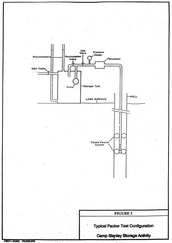
The zones will be determined from the lithologic core and downhole geophysical results. A packer consists of a rubber sleeve that expands against the wall of the borehole when pressure is applied. The testing of isolated sections of a borehole requires the use of two pneumatic isolation packers separated by a length of perforated pipe. The double-packer assembly and inflating line are then lowered into the borehole on a string of pipe so the perforated section is opposite the interval to be tested. Figure 3 illustrates a typical packer test design.
Prior to each packer test a check should be made to ensure that the injection tubing is completely filled with water. The packers should be inflated initially with the valves open. The line valve should then be closed, and the pump started with the recirculation valve open. To initiate the test the line valve is opened and the recirculation valve closed simultaneously.
At the rates of fluid injection anticipated in the tests, it may be difficult to maintain either a constant rate of injection or a constant injection pressure during field operations. It is therefore imperative that both pressure and injection rates be measured and recorded over time throughout the test. Measurements should be made as frequently as possible during the early moments of the test.
Figure 3 - Packer Test Design
The period of injection should continue for up to 1 hour. As the time of injection continues, changes in pressure and injection rate will occur more slowly and frequency of measurement may be decreased. However, measurements should be taken at least every 5 minutes until the end of the injection period. Pumping times and pressures depend on the depth and requirements of the test and the nature of the materials being tested. As far as the length of time to run the test is concerned, the general rule is to run the test until an equilibrium condition is established. This is considered to have been reached when four or five readings of pressure and flow taken at approximately 5-minute intervals are essentially constant. Past experience shows that most tests reach an equilibrium in about 30 minutes.
The hole must be cleaned of all cuttings and drilling mud (if used) prior to testing. Appendix C provides worksheets for monitoring the injection system and calculating results of the packer tests.
The spacing of packers (which governs the length of the test section) is generally between 5 and 10 feet apart, depending on the diameter of the hole. The minimum spacing of packers should be governed by the following guideline:
Sp/D > 5
Where:
Sp = the spacing, or length between packers, and
D = the diameter of the borehole.
Permeability is calculated from the following formulas:
For the unsaturated zone (Zone 1) above the water table:
K = Q/Cu*r*H
For the saturated zone (Zone 2) above the water table:
K = 2Q/(Cs*r)(Tu+H-A)
For the saturated zone (Zone 3) below the water table:
K = Q/Cs*r*H
Where:
K = Permeability (ft/sec)
Q = Flow (cubic ft/sec)
A = Length of test section (ft)
r = Radius of the test hole (ft)
Cu = Conductivity coefficient for unsaturated materials with partially penetrating cylindrical test wells (obtained from Chart A in Appendix A).
Cs = Conductivity coefficient for semi-spherical flow in saturated materials with partially penetrating cylindrical test wells (obtained from Chart B from Appendix C).
Tu = Distance in feet from the water surface in the well to the water table; (Tu = bu-D+H) where:
bu = Thickness of unsaturated material (ft)
D = Distance from the ground surface to the bottom of the test section (ft)
H = Effective head in feet (h1 + h2 � L) where:
h1 = (above the water table) distance between the Bourdon gauge and the upper-surface of the lower packer (ft)
h1 = (below water table) distance between the gauge and the water table (ft)
h2 = Applied pressure at the gauge (1 psi = 2.307 ft of head)
L = Head loss in feet due to friction:
L = 10.44*PL*Q1.85/c1.85*d4.865)
PL = Length of drill pipe (feet)
Q = Flow (gal/min)
c = 140 (Pipe surface roughness coefficient)
d = Diameter of pipe (in)
For these equations to be valid, the thickness of each packer must be > 10 times the radius of the test hole.
2.9 - Discrete Interval Groundwater Samples
At the discretion of CSSA, a total of 51 discrete interval groundwater samples will be collected from up to 13 well locations listed in Tables 1and 2, and analyzed for those parameters listed in Table 4. As many as five samples per hydrogeologic zone will be obtained using an inflatable packer system. A turn-around-time of 1, 3, or 7 days will be requested based on the urgency of the data to make informed decisions.
In a 4-inch corehole, a double packer system shall be used to straddle either a submersible pump or screened inlet section, based on the yield of the formation at that depth. The packer system�s open interval will not exceed 12 feet. The straddle packer system may be implemented either during or after the completion of the corehole, but prior to reaming. When the formation freely yields groundwater as determined by the site geologist, a pump shall be used to purge and collect discrete groundwater samples. When the formation does not freely yield groundwater, the test zone shall be purged via air lifting, followed by sample collection with a �-inch diameter bailer. The minimum purge volume shall be 1.5 pore volumes. Ideally, three to five volumes shall be removed before sampling. The site geologist may require greater volumes to be removed to reduce turbidity or improve other quality parameters prior to sample collection.
For the collection of discrete groundwater samples at locations other than the corehole, the boring will be specifically reamed to a 6-inch diameter to accommodate a similarly sized packer system. The 6-inch packer system consists of a single packer set above a submersible electric pump with no check valve. The total depth of the borehole shall serve as the lower isolation point for the discrete sample; therefore, the sampling must occur as drilling progresses in depth. Purging and sampling methods and volumes are the same as with the 4-inch packer system, and are entirely dependent upon the amount of water yielded by the discrete interval.
2.10 - Well Upgrades
A total of five existing wells will be upgraded or retrofitted to conform to CSSA groundwater monitoring strategy. The existing wells include two monitoring wells (CS-MW1-LGR and CS-MW2-LGR) with an open borehole completion and surface casing. The remaining three wells are older agricultural wells (CS-16, CS-G and CS-H) that require rehabilitation. Upon completion, CS-16 will be referred to as CS-MW16-LGR. Table 7 lists the known specifications of the existing wells.
Table 8 lists the specific tasks for the well upgrades. Specifically, the subcontractor will retrofit existing wells CS-MW1-LGR, CS-MW2-LGR with 3-inch ID PVC casing and 25 feet of stainless steel, 0.050-inch wire-wrapped well screen. With exception of the 3-inch well diameter, installation will follow the requirements of the other wells. Well CS-16 will be upgraded with 4-inch ID PVC casing and 25 feet of stainless steel, 0.050-inch wire-wrapped well screen. CS-MW1-LGR AND CS-MW2-LGR will be plugged back with bentonite. Well CS-MW16-LGR will be plugged back with 110 feet of grout, and topped off with 11 feet of bentonite to 310 feet bgl.
The existing low-flow bladder pumps and submersible pumps (CS-MW16-LGR only) will be temporarily removed during the upgrade. If the existing well pad is cracked or otherwise compromised, the pad will be removed and replaced. Well development will follow completion of the upgrade to develop the filter pack and formation. Existing pumps will require replacement upon completion of the upgrade activities.
Table 7 - Completion Information for Existing Wells
| ID | Total Depth (feet bgs) | Casing Depth(feet bgs) | Casing Inside Diameter (inches) | Open Borehole Diameter(inches) | Lower Glen Rose / Bexar Shale Contact (feet bgs) |
| CS-MW-1-LGR | 320 | 140 | 6 | 6 | 313 |
| CS-MW-2-LGR | 361 | 141 | 6 | 6 | 343 |
| CS-MW-16-LGR | 431 | 200 | 6 | 10 | 310 |
| CS-G | 336 | 250 estimated | 5.5 | Unknown | Unknown |
| CS-H | 320 | Unknown | Unknown | Unknown | Unknown |
| Notes: -CS-MW-1 and CS-MW-2 were installed by GeoProjects, International during April 1996. -Completion records for Wells G and H are not available. Measured total depths were by GeoProjects, International during February 2001. |
Table 8 - Tasks for Well Upgrades
| ID | Remove Existing Structure or Pad | Remove Existing Tubing | Plug Back (feet) | Install Casing-Screen(feet) | Surface Completion | Re-develop Well | Install submersible pump | Install Low-Flow Pump |
| CS-MW-1-LGR | � | | � (7) | � (313) | � | � | | � Re-install |
| CS-MW-2-LGR | � | | � | � (343) | � | � | | � Re-install |
| CS-MW-16-LGR | | � | � (121) | � (310) | | � | � Re-install | � Re-install |
| CS-G | � | | | | � | � | | � New |
| CS-H | � | � | | | � | � | � New | |
Remnants of the old windmill structure and foundation will be removed at Well CS-G. The existing flush-mounted surface casing will require upgrading to a 3-foot stick-up. A new surface completion that includes a 4-foot square pad, locking stick-up protector, and bollard posts will be installed. The well will be re-developed to remove stagnated water, scale, and sediment accumulation.
Re-completion of Well CS-H includes removing the pump from the top of the well and attempting removal of the tubing from the well. If the tubing can be removed, the subcontractor will determine the total depth of the well, install a high capacity submersible pump, and complete the electrical hook-up already present at the well. The submersible pump will be rated to discharge 20 gallons per minute at a total dynamic head of 350 feet.
If the tubing cannot be removed, Well CS-H will be plugged and abandoned and a replacement LGR well drilled at that approximate location provided the task has been funded. The project manager will need to be contacted to confirm that the funding mechanism is in place before Well CS-H is plugged and abandoned, and a replacement well is drilled. A replacement well installation will follow a typical single-cased well design. It is anticipated the replacement well drilling will also include continuous coring as well as geophysical and video surveying.
2.11 - Transducer and Pump Installations
Low flow pumps will be purchased and installed in 14 wells. The pumps will be pneumatically-operated bladder pumps consistent with the monitoring system already existing at CSSA. As specified in the SOW, the low-flow pumps will be installed in all wells listed in Table 1, with exception of CS-H, which will be retrofitted with an electric submersible pump.
Dataloggers and transducers consistent with the system already utilized at CSSA will be installed and monitored quarterly at 14 well locations as given in Table 1. As given in the DQOs, the selected well locations will be CS-MW1-LGR, CS-MW2-LGR, CS-MW2-CC, CS-MW11-LGR, CS-MW12-LGR, CS-MW12-CC, CS-MW15-LGR, CS-MW15-CC, CS-MW17-LGR, CS-MW18-LGR, CS-MW19-LGR, CS-9, CS-10, and CS-11.
2.12 - Monitoring Well Development
A total of 22 wells (17 new wells and five upgraded wells will be developed by the drilling subcontractor using surging, bailing, and pumping techniques. The well development requirements follow the MFSP AFCEE document. The monitor well development requirements are: (1) all newly-installed monitor wells shall be developed no sooner than 48 hours after installation to allow for grout curing; (2) all drilling fluids used during well construction shall be removed during development; (3) wells shall be developed using surge blocks and bailers or pumps (prior approval for any alternate method shall be obtained, in writing, from AFCEE before well construction begins), and wells shall be developed until: (a) the turbidity remains within a 10 nephelometric turbidity unit range for at least 30 minutes; and (b) all stabilization criteria are met, including: temperature � 1oC, pH � 0.1 units, and electrical conductivity � 5 percent; (4) discharge water color and volume shall be documented; (5) no sediment shall remain in the bottom of the well; (6) no detergents, soaps, acids, bleaches, or other additives shall be used to develop a well; and (7) all development equipment shall be decontaminated according to the specifications of this document. Well development measurements will be recorded in the logbook, and on a form such as that presented in Appendix D.
In the interest of time, development activities may occasionally progress in stages while the grouting process is occurring. Often, a well requires numerous events to top off settling grout in either the inner or outer casings. This process may take place over a period of several days. Development may begin once more than 50 percent of the inner casing grout has been emplaced. However, in accordance with AFCEE requirements, no development activity will be engaged within the 48-hour time period after the emplacement of any lifts of grout (inner or outer casings).